OpenFOAM
Contents
Quick summary

Developed by: 2018 (OpenFOAM release v1812)
Date: May 2018 (Version 2.8)
Type: Tool
Suitable for the following [[::Category:Measures|measures]]:
Introduction
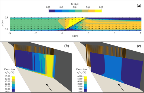
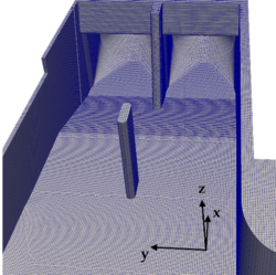
OpenFOAM is a C++ toolbox for simulation of general continuum mechanics problems including the Navier-Stokes equations that mathematically describe the 3D motion of fluids. For simulations of free-surface gravity flows, the prebuilt Eulerian’ solver interFOAM is most suitable. The interFOAM solver identifies the interface between water and air based on the Volume Of Fluid (VOF) method and uses the PIMPLE algorithm for pressure-velocity coupling. The governing flow equations can be solved in combination with different approaches for turbulence modelling. In OpenFOAM, Reynolds-averaged Navier-Stokes (RANS) models using one or two equation turbulence models (e.g. k-ε model) as well as more computationally expensive large eddy simulation (LES) methods are available. An advantage of OpenFOAM, besides its free availability, is the use of body-fitted or unstructured computational grids. The additional use of polyhedral cells (in addition to hexahedral cells) allows even complex geometries to be accurately mapped (Figure 36).
Application
The operating system for OpenFOAM is Linux and there is no official Graphical User Interface (GUI). The basic directory structure for an OpenFOAM case containing the minimum set of files required to run an application is shown in Figure 37. All the files can be accessed with a text editor. In the system directory, the parameters associated with the solution procedure itself are defined (e.g. start/end time, solution schemes). The constant directory contains the description of the mesh and files specifying the physical properties. The time directories contain data files that can be either initial values, boundary conditions or results written to file.
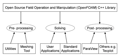
OpenFOAM is supplied with a pre- and post-processing environment. The interface to the pre- and post-processing are OpenFOAM utilities, thereby ensuring consistent data handling across all environments. The overall structure of OpenFOAM is shown in Figure 38. In the pre-processing, simple meshes containing blocks of hexahedral cells can be generated by the blockMesh utility. For more complex geometries, the snappyHexMesh utility automatically generates meshes containing split-hexahedral cells by iteratively refining the starting mesh and morphing the resulting split-hex mesh to the triangulated surface of solid geometrical structures like power plant facilities (see Figure 37). Solid structures are represented in the form of stereolithographic files (STL). The main post-processing tool provided with OpenFOAM is the reader module paraFoam that uses ParaView, an open-source visualization software to display geometry, computational mesh and simulation results (Figure 38).
Other information
General advantages & disadvantages of the tool (no claim for completeness)
|
Pros |
Cons |
|
Open source software |
Complex model setup (no GUI) |
|
Accurate representation of complex geometries due to unstructured or body-fitted computational grids |
Definition of boundary and initial condition requires in depth knowledge of underlying concepts |
|
Growing user community (forum) |
No standardized documentation |
Relevant literature
- Feigenwinter, L., Vetsch, D., Kammerer, S., Kriewitz, R.C., Boes, R.M. (2018) Conceptual Approach for Positioning of Fish Guidance Screens Using CFD and expert knowledge. Sustainability, under review.Fuentes-Perez, J.F., Silva, A.T., Tuhtan, J.A., Garcia-Vega, A., Carbonell-Baeza, R., Musall, M., Kruusmaa, M. (2018). 3D modelling of non-uniform and turbulent flow in vertical slot fishways. Environmental Modelling and Software, 99, 156-169, doi:10.1016/j.envsoft.2017.09.011.
- Gisen, D.C., Weichert, R.B,; Nestler, J.M. (2017) Optimizing attraction flow for upstream fish passage at a hydropower dam employing 3D Detached-Eddy Simulation. Ecological Engineering, 100, 344-353, doi:10.1016/j.ecoleng.2016.10.065.
- Raynal, S., Chatellier, L., David, L., Courret, D., Larinier, M. (2013). Numerical Simulations of Fish-Friendly Angled Trashracks at Model and Real Scale. Proceedings of the 35th Iahr World Congress, Vols I and II, 2557-2566.
Contact information
OpenFOAM download: https://www.openfoam.com / https://openfoam.org
User guide and tutorials: https://www.openfoam.com/documentation
Paraview: https://www.paraview.org


