Dilution gauging
Contents
Quick summary

Developed by:
Date:
Type: Method
Suitable for the following [[::Category:Measures|measures]]:
Introduction
This method requires the release of a known tracer concentration in a section of the river or fishway and the subsequent determination of the tracer concentration in a downstream section. It is based on the dilution relationships between the injection of the tracer and the discharge we want to know. There are two main different methods for the injection of the tracers into the flow: (a) instantaneous or integration method and (b) continuous method.
The discharge for (a) is calculated as:
Q= c_0/c∙V/T
Being c_0 the tracer concentration which is introduced in the watercourse with discharge Q. c is the concentration of the sample in volume V and T is equal to the time needed for the tracer to be transported downstream.
The formulae discharge for (b):
Q=q.c_1/c_2
Being c_1 the tracer concentration in the injection, q the constant injection flow for the tracer (e.g. using a Mariotte device) and c_2 the tracer concentration at the downstream point.
The choice of the tracer depends on several factors: the chemical characteristics of the water, the suspended sediment, the distance between the injection and measuring section, the type of flow to be measured, the sensitivity of the tracer measurement devices and the possible environmental impact of the tracer. Common tracers used: chemical (NaCl, NaI, NH4Cl) and fluorescent (fluorescein and Rhodamine WT).
It is important to verify some conditions: the tracer cannot be absorbed in the medium and the solution must be well mixed. Emphasizing the last one, it is necessary to assure the good mixing length, which is the distance between the injection and measure sections ensuring a stable concentration of the diluted tracer.
Application
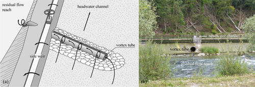
Within the scope of FIThydro, a BMS consisting of a geophone and accelerometer was installed on the vortex tube at HPP Schiffmühle, which diverts bedload from the headwater channel to the residual flow reach. The vortex tube consists of a steel tube embedded in the side weir, connecting the two parallel channels (Figure 2). A gate valve is positioned in the side weir, which opens automatically when a predefined discharge is exceeded. The opening of the valve automatically triggers the BMS measurements.
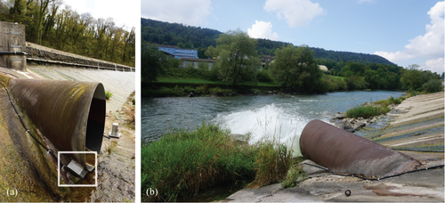
In contrast to the SPGS, the steel tube is used as an impact plate for the BMS and the sensors are mounted directly onto the outside of the steel tube (Figure 3). Therefore, laboratory calibration was not easily possible. Instead, the system was calibrated in the field by repeatedly dumping sediment samples of known grain size distribution and volume upstream of the vortex tube and subsequently flushing them to the residual flow reach. In addition, drop tests with single grains were performed when the vortex tube was not in operation. The single grain signals help to analyze the influence of grain size, grain form, drop height, and drop location on the amplitude and frequency signals.
The first results of the presented BMS are promising, but the data analysis will be further refined and extended. Furthermore, a larger number of recorded flood events is necessary to check the plausibility of the results obtained so far. Overall, it is demonstrated that the measurement principle of the state-of-the-art SPGS can be extended to non-standardized impact plates like steel vortex tubes, and the use of an additional accelerometer sensor, given that appropriate calibration measures are taken.
Other information
The total costs for the geophone and accelerometer sensors amount to approx. 885-1'330 €. The costs for the field computer, the analog-digital-converter, and the 3G modem are approx. 5'300-6'200 €. Additional costs for the installation, data transmission, and the calibration depending on the site conditions and set-up.
Relevant literature
- Albayrak, I., Müller-Hagmann, M., Boes, R.M. (2017). Calibration of Swiss Plate Geophone System for bedload monitoring in a sediment bypass tunnel. In Proc. 2nd Intl. Workshop on Sediment Bypass Tunnels (Sumi, T., ed.), paper FP16, Kyoto University, Kyoto, Japan
- Gray, J.R., Laronne, J.B., Marr, J.D.G. (2010). Bedload-surrogate Monitoring Technologies, US Geological Survey Scientific Investigations Report 2010-5091. US Geological Survey: Reston VA.
- Rickenmann, D., Turowski, J.M., Fritschi, B., Klaiber, A., Ludwig, A. (2012). Bedload transport measurements at the Erlenbach stream with geophones and automated basket samplers. Earth Surface Processes and Landforms, 37, 1000-1011.
- Rickenmann, D., Turowski, J.M., Fritschi, B., Wyss, C., Laronne, J., Barzilai, R., Reid, I., Kreisler, A., Aigner, J., Seitz, H., Habersack, H. (2014). Bedload transport measurements with impact plate geophones: comparison of sensor calibration in different gravel-bed streams. Earth Surface Processes and Landforms, 39, 928-942.
- Wyss, C.R., Rickenmann, D., Fritschi, B., Turowski, J.M, Weitbrecht, V., Boes, R.M. (2016a). Laboratory flume experiments with the Swiss plate geophone bed load monitoring system: 1. Impulse counts and particle size identification. Water Resources Research, 52, 7744-7759.
- Wyss, C.R., Rickenmann, D., Fritschi, B., Turowski, J.M, Weitbrecht, V., Boes, R.M. (2016b). Laboratory flume experiments with the Swiss plate geophone bed load monitoring system: 2. Application to field sites with direct bed load samples. Water Resources Research, 52, 7760-7778.

