Difference between revisions of "FLOW-3D"
Bendikhansen (talk | contribs) |
Bendikhansen (talk | contribs) |
||
| Line 1: | Line 1: | ||
[[file:flow3_logo.png|250px|right]] | [[file:flow3_logo.png|250px|right]] | ||
=Quick summary= | =Quick summary= | ||
| − | |||
[[file:flow3d_xyz.png|thumb|250px|Figure 1: Location of variables in FLOW-3D computational mesh (source: FLOW-3D)]] | [[file:flow3d_xyz.png|thumb|250px|Figure 1: Location of variables in FLOW-3D computational mesh (source: FLOW-3D)]] | ||
[[file:flow3d_hpp.png|thumb|250px|Figure 2: Figure 41: Example of a river power plant geometry set up for FLOW-3D (source: VAW)]] | [[file:flow3d_hpp.png|thumb|250px|Figure 2: Figure 41: Example of a river power plant geometry set up for FLOW-3D (source: VAW)]] | ||
| Line 28: | Line 27: | ||
The software license includes the post-processing tool FlowSight, designed to deliver sophisticated visualizations of FLOW-3D results. Arbitrary 2D clips along spline pathways, 3D clips and transparencies, volume rendering, advanced data time series plotting and calculators, streamline and vector plots are available in FlowSight (Figure 3 and 4). Alternatively, the result files can be visualized using other free (e.g. ParaView) or commercial (e.g. Tecplot) CFD visualization software. | The software license includes the post-processing tool FlowSight, designed to deliver sophisticated visualizations of FLOW-3D results. Arbitrary 2D clips along spline pathways, 3D clips and transparencies, volume rendering, advanced data time series plotting and calculators, streamline and vector plots are available in FlowSight (Figure 3 and 4). Alternatively, the result files can be visualized using other free (e.g. ParaView) or commercial (e.g. Tecplot) CFD visualization software. | ||
| + | |||
| + | =Mitigation measures where MTD might be applied= | ||
| + | {{Suitable measures for FLOW-3D}} | ||
=Other information= | =Other information= | ||
Revision as of 12:59, 20 January 2020
Contents
Quick summary
Developed by: Flow Science, Inc (Santa Fe, New Mexico, USA)
Date: 2016 (FLOW-3D release v11.2)
Type: Tool
Introduction
FLOW-3D is a commercial CFD simulation software that focusses on free-surface flows in a wide range of industrial applications and physical processes. The software solves the Navier-Stokes equations that mathematically describe the 3D motion of fluids. The domain is subdivided into several mesh blocks containing rectangular grid cells (structured mesh). Fluid velocities and pressures are located at staggered mesh locations as shown for a typical grid cell in Figure 1.
The numerical model involves the following variables: velocities (u,v,w) and fractional areas (A) at the centers of cell-faces, pressures (P), fluid fractions (F), fractional volumes (VF), densities (ρ), internal energy (I), turbulence quantities for energy (q), dissipation (D) and viscosity (μ) are located at cell centres.
In FLOW-3D, one or two equation turbulence models (e.g. k-ε model), as well as more computationally expensive large eddy simulation (LES) methods, are available for turbulence modelling. Wall boundaries and other solid geometrical structures like power plant facilities are embedded in the orthogonal mesh by the so called FAVORTM method. This algorithm defines the fractional face areas and fractional volumes of the cells that are open to fluid flow. Thus, the mesh does not have to be fit around complex geometry during the pre-processing. In order to properly capture the free-surface dynamics, the Volume of Fluid (VOF) method is applied in FLOW-3D.
Application
FLOW-3D supports Windows as well as Linux platforms and includes a powerful graphical user interface (GUI) which supports the user during the model setup and simulation process. 3D solid structures are imported into the GUI in the form of stereolithographic files (STL). Figure 2 shows the exemplary geometry set-up of the FIThydro case study hydropower plant (HPP) Bannwil in Canton Bern, Switzerland for FLOW-3D. Definition of mesh blocks and mesh resolution, as well as boundary and initial conditions, can is done in the GUI. The use of multiple mesh blocks allows for local refinement at areas of interest. Small obstacles, complex geometries and thin channels that are small compared to the overall domain size can be accurately resolved using so called conforming mesh blocks. In FLOW-3D “conforming mesh” means, that the transition between solid and void or solid and fluid is resolved with a nested finer mesh within a defined overlap length compared to the surrounding block.
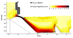
The software license includes the post-processing tool FlowSight, designed to deliver sophisticated visualizations of FLOW-3D results. Arbitrary 2D clips along spline pathways, 3D clips and transparencies, volume rendering, advanced data time series plotting and calculators, streamline and vector plots are available in FlowSight (Figure 3 and 4). Alternatively, the result files can be visualized using other free (e.g. ParaView) or commercial (e.g. Tecplot) CFD visualization software.
Mitigation measures where MTD might be applied
Other information
In addition to the use on regular Windows and Linux workstations, the High Performance Computing (HPC) version of FLOW-3D is designed to run on distributed memory computer clusters allowing engineers to tackle problems with very large computational domains or long simulation time. For users with limited access to hardware resources, the HPC version is also available on the FLOW-3D CLOUD computing service.
General advantages & disadvantages of the tool (no claim for completeness)
|
Pros |
Cons |
|
Relatively easy to use due to GUI and integrated pre and post-processing |
Commercial software (licenses costs) |
|
Detailed documentation available |
Source code not available |
|
Access to HPC services via Cloud |
Cartesian gird |
Relevant literature
- Kammerer, S., Lutz, N., Vetsch, D., Kriewitz, K. R., Früh, H. (2018). Beurteilung der Unterhaltspflicht eines Regulierwehrs mit Kraftwerk mittels 3D Simulationen, 19. Wasserbausymposium Graz 2018, *Graz, Austria, pp.237-244, Graz: Verlag der Technischen Universität Graz, September 18-20.
- Duguay, J., Lacey, R.W.J., Gaucher, J. (2017). A case study of a pool and weir fishway modeled with OpenFOAM and FLOW-3D. Ecological Engineering. 103. 31-42. doi: 10.1016/j.ecoleng.2017.01.042.
- Duguay, J., Lacey, R.W.J. (2014), Use of Numerical Hydraulic Modeling to Improve Fish Passage at Perched Culverts. Canadian Journal of Civil Engineering, 2016, 43(2): 173-181. dx.doi.org/10.1139/cjce-2014-043
Contact information
FLOW-3D webpage: https://www.flow3d.com/
Water & Environmental applications: https://www.flow3d.com/industries/water-environmental/


