Difference between revisions of "Skimming walls (fixed or floating)"
Bendikhansen (talk | contribs) |
Bendikhansen (talk | contribs) m (Text replacement - "=Useful MTDs=" to "=Relevant MTDs and test cases=") |
||
| Line 10: | Line 10: | ||
=[[Methods, tools, and devices]]= | =[[Methods, tools, and devices]]= | ||
| − | = | + | =Relevant MTDs and test cases= |
{{Suitable MTDs for Skimming walls (fixed or floating)}} | {{Suitable MTDs for Skimming walls (fixed or floating)}} | ||
Revision as of 14:21, 21 January 2020
Contents
Introduction
Skimming walls (or surface mask) can be used to deflect those species that migrate in the surface layers, such as salmonid smolts. This device is inefficient for bottom-oriented species, such as eels. A guide wall must cover a certain depth to generate a sufficient repelling effect and must be installed at an angle to the channel intake to guide fish to a bypass entrance located at its downstream end.
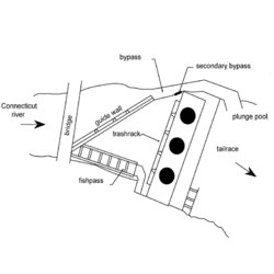
Such a device has been installed on the East Coast of the USA at the Bellow Falls power station (Connecticut River, maximum turbine discharge 410 m3/s). The wall extends vertically halfway down the 9 m deep water column, at an angle of 40° across the channel and guides fish towards a sluice gate and a channel leading to the tailrace. An auxiliary bypass located near the bar rack is intended to accommodate fish which have passed under the wall. The efficiency of the guide wall was estimated at 84%, with 10% of the smolts passing through the secondary bypass and 6% through the turbines. The efficiency of the device is probably closely related to the angle of the wall with respect to the flow and above all to the depth (4.5 m) at which the wall is submerged (Odeh , et al., 1998).
In France, the application of skimming walls is reserved to large HPP only, where other solutions are not feasible.
Methods, tools, and devices
Relevant MTDs and test cases
During planning
Planning of skimming walls requires a comprehensive study on fish behaviour to assess when and where fish move on their downstream migration. This can be conducted by telemetry experiments or visual observations with video or sonar technology. River hydraulics at the intake must be modelled by 2D or 3D CFD software if needed. The physical installations of the skimming wall must be planned according to the power plant geometry and construction works must be adapted to physical forces and the hydropower scheme.
During implementation
The physical installations of skimming wall must be planned according to the power plant geometry and construction works must be adapted to physical forces and the hydropower scheme.
During operation
A skimming wall doesn’t need maintenance as cannot be clogged.
Classification table
| Classification | Selection |
|---|---|
| Fish species for the measure | All |
| Does the measure require loss of power production | Operational (requires flow release outside turbine) |
| - | |
| - | |
| Recurrence of maintenance | Never |
| Which life-stage of fish is measure aimed at | - |
| - | |
| - | |
| - | |
| - | |
| Movements of migration of fish | |
| Which physical parameter is addressed | N/A |
| - | |
| - | |
| - | |
| - | |
| - | |
| - | |
| - | |
| Hydropower type the measure is suitable for | Plant in dam |
| Plant with bypass section | |
| Dam height (m) the measure is suitable for | All |
| Section in the regulated system measure is designed for | - |
| Upstream of hydropower plant | |
| - | |
| - | |
| River type implemented | - |
| Fairly steep with rocks, boulders (from 0.4 to 0.05 %) | |
| Slow flowing, lowland, sandy (less than 0.05 %) | |
| Level of certainty in effect | Moderately certain |
| Technology readiness level | TRL 9: actual system proven in operational environment |
References
- Odeh , M und Orvis, C. 1998. Downstream Fish Passage Design Considerations and Developments at Hydroelectric Projects in the North-east USA. 1998.
